1 (edited by kittensauce 2016-09-27 18:29:47)

Topic: Replacing the Chumby One screen?

Hello. I have owned a Chumby One for several years, however, I have not used it for the most of those several years. Now that I know more about the internal workings of technology, I would like to mess around with the Chumby instead of using it as a simple (well, it's not really that simple, is it?) alarm clock. However, at some point in time, I must have dropped it, as there are a few lines across the screen. They don't block much, and I could probably live with them, but it's just ever so slightly irritating. Everything else with the Chumby is working absolutely fine, except the power supply, which I don't find very surprising. After doing some looking around, I could not find any replacement Chumby One screens, and the official Chumby Store no longer sells power supplies. Does anyone know where I might be able to get either of these? Thanks, in advance.
On a side note, is there some sort of introduction subforum/thread?

Breaking everything, one screw at a time.

Re: Replacing the Chumby One screen?

I'll see if I can find a replacement screen for you in storage.

I have the parts to make some more C1 power supplies, I'll put some together and get them up on the store.

3 (edited by kittensauce 2016-09-27 18:40:06)

Re: Replacing the Chumby One screen?

Duane wrote:

I'll see if I can find a replacement screen for you in storage.

I have the parts to make some more C1 power supplies, I'll put some together and get them up on the store.

Okay, thank you! Just to be sure, the Chumby
screen turning white (with a few lines at times) when plugged into different power outlets and turning off randomly and turning on again once I jiggle around the power supply plug is due to the power supply, correct? Or does my Chumby have some other issue that I'm not aware of?

Breaking everything, one screw at a time.

Re: Replacing the Chumby One screen?

If it's about jiggling the barrel connector in the back of the device, it's more likely some damage to the connector, probably torn away from the circuit board.  I've fixed a couple of those, can't check unless the device is opened up.

If you're talking about jiggling the power supply itself, then it's more likely the power supply.

Re: Replacing the Chumby One screen?

Duane wrote:

If it's about jiggling the barrel connector in the back of the device, it's more likely some damage to the connector, probably torn away from the circuit board.  I've fixed a couple of those, can't check unless the device is opened up.

If you're talking about jiggling the power supply itself, then it's more likely the power supply.

Oh my, yes, I did mean jiggling the barrel that's connected in the back of the device, I just wasn't sure what it was called. Is the white screen due to a torn power connector too?

If I'm still wrong about the definition of the "barrel", I took an image just to make sure: imgur(dot)com/Rvo5lnO(dot)jpg

Breaking everything, one screw at a time.

Re: Replacing the Chumby One screen?

Does the socket in the device seem to be loose, if you try to wiggle it gently with a pencil?

7 (edited by kittensauce 2016-09-28 12:43:50)

Re: Replacing the Chumby One screen?

Duane wrote:

Does the socket in the device seem to be loose, if you try to wiggle it gently with a pencil?

Yes, in fact, it does!
...I sure hope it still (semi-)works, seeing as I just stuck a pencil into it, even if it's probably going to get replaced anyway.

[EDIT] I just realized the "Service, Warranty & Repair" subforum exists, and that I've probably should've made this topic there. Oh well, it doesn't really matter now.

Breaking everything, one screw at a time.

8 (edited by demarks51 2016-09-29 11:43:14)

Re: Replacing the Chumby One screen?

Sounds like contacts of the power entry port are loose. If you are good with soldering you can firm it up. It can be a little tedious. There is a visual breakdown site for the Chumby one somewhere to guide you to open up the unit. I am not very good at soldering small wires but it may be worth a shot.
https://www.ifixit.com/Teardown/Chumby+ … rdown/1614
Above is the link to the teardown for a Chumby One. Hope this helps.

Owner of 3 Sony Dash, 2 Info 8.

Re: Replacing the Chumby One screen?

Typically in this situation the trace has been lifted from the board and broken - wiggling make an intermittent, or at best poor, connection.

What I generally do to repair this type of problem is to glue down the connector and run a wire trace to another part of the board with the same signal.  Depending upon which trace is broken (GND or +5V) you have to route to different places.

10 (edited by kittensauce 2016-10-02 12:24:40)

Re: Replacing the Chumby One screen?

demarks51 wrote:

Sounds like contacts of the power entry port are loose. If you are good with soldering you can firm it up. It can be a little tedious. There is a visual breakdown site for the Chumby one somewhere to guide you to open up the unit. I am not very good at soldering small wires but it may be worth a shot.
-snip-
Above is the link to the teardown for a Chumby One. Hope this helps.

Well, I can solder, and the pads look faily large, but I haven't seen the size of them in reality (only on a computer screen) - and I've already learned my lesson with DSi NAND solder pads. (They looked large online, but in reality they were about the width of the tip of a sewing needle!) I should be able to get help from someone, though, probably a relative who has more experience in soldering than me.

[EDIT] Ah, they look pretty big. Looks like it's damaged in some other way, though.

Duane wrote:

Typically in this situation the trace has been lifted from the board and broken - wiggling make an intermittent, or at best poor, connection.

What I generally do to repair this type of problem is to glue down the connector and run a wire trace to another part of the board with the same signal.  Depending upon which trace is broken (GND or +5V) you have to route to different places.

Sounds good - looks like I'll be opening this thing soon. However, when I am to solder, I have a question: which wire is preferable? Solid copper core 30AWG or something else? And would rosin core solder be usable?

[EDIT] Hey, quick question, does the Chumby work without a microphone? Because it looks like I don't have one any more, I pulled the wires out of the plug thing and then snapped the plug thing in half. Whoops!
Here's an image of my power port: imgur(dot)com/KLcavdV
And from what I read online - aren't there supposed to be NTSC/PAL solder pads somewhere? Were there different revisions of the Chumby One?

Breaking everything, one screw at a time.

Re: Replacing the Chumby One screen?

There was only the Falconwing chumby one.  I don't think there were any major differences, but Duane or somebody with more knowledge about the hardware runs will have to confirm.

As for the NTSC/PAL, I believe the same pads are used, but there are code changes to differentiate.  Unfortunately the picture itself is gone, but maybe one of the admins has a copy.  I looked in my mirrors and old files and didn't find it but you can read what is available here:
http://wiki.chumby.com/index.php?title= … chumby_One

The wiki is actually pretty well curated and contains a lot of great information for these awesome devices.  Here's the main page: http://wiki.chumby.com/index.php?title=Main_Page

Linux Guy - Occasional Chumby Hacker

Re: Replacing the Chumby One screen?

There were two C1 devices, the difference being a different factory that was manufacturing them - actually there was a third one, a prototype, but I don't think there are any in the wild.

I believe the first will show as HW 10.6, and the other as HW 10.8, and there are close to the same number of each in the field.  One way to tell the difference is the the blue band on the front is a little wider in the 10.8 version.  The same factory that built the 10.8 version also built the C8.  The 10.6 version was built by the factory that built the I3.5 and I8.  I think the 10.8 version also came with a better power supply.

The internal electronics are more or less the same.

The device will work just fine without the microphone attached.

Re: Replacing the Chumby One screen?

For the short distance you're running it, 30AWG will probably make do (I calculated the voltage drop to be <0.1V for about 3 inches), but if you have anything larger (I'd suggest at least 24AWG, such as one of the conductors from CAT5 cable) that would be better. Doesn't matter much if it's stranded or solid, and yes rosin core solder is fine, that's what's used in all electronics -- acid core, on the other hand, should only be used for plumbing!

If you're comfortable doing so, you may look into removing the jack from the board entirely; I had a laptop whose jack suffered the same fate, and I removed it and put a panel-mount jack in the laptop's case with a pigtail running directly to some nice large power contacts on the board. Of course this tethers the board to the case, but it's a more mechanically sound solution, as the connect/disconnect force is borne by the case instead of a couple of soft bits of metal wink

Should you do the above, try to use at least 20-22AWG, and keep the pigtail long-ish (maybe a foot or so) so if you need to crack it open again you have some room.

Re: Replacing the Chumby One screen?

Sorry for not replying sooner; I've been busy being lazy. smile
Also, I was away from my Chumby for a while. Probably doesn't have anything to do with my laziness, though.
Thank you for all the replies, though! It's good to see that this old alarm clock isn't quite dead yet (and hopefully never will be)!

Materdaddy wrote:

As for the NTSC/PAL, I believe the same pads are used, but there are code changes to differentiate.  Unfortunately the picture itself is gone, but maybe one of the admins has a copy.  I looked in my mirrors and old files and didn't find it but you can read what is available here:
-snip-

I've actually seen that page before, that's where I got the idea to attempt such a feat in the first place tongue
I've also managed to find the image (it's on bunnie's blog), but it seems that the image was of the older motherboard (see below), and I apprently have the newer 10.8 motherboard.


Duane wrote:

There were two C1 devices, the difference being a different factory that was manufacturing them - actually there was a third one, a prototype, but I don't think there are any in the wild.

I believe the first will show as HW 10.6, and the other as HW 10.8, and there are close to the same number of each in the field.  One way to tell the difference is the the blue band on the front is a little wider in the 10.8 version.  The same factory that built the 10.8 version also built the C8.  The 10.6 version was built by the factory that built the I3.5 and I8.  I think the 10.8 version also came with a better power supply.

I suppose I have the 10.8 version... because I don't have the 10.6 version? At least, from what I've seen, 10.6 boards say "HW Code 10.6", and since mine doesn't say that... well, I think you get the idea.
Although, it doesn't say "HW Code 10.8" either, which is a little strange.

Duane wrote:

The internal electronics are more or less the same.

Except for the location of the video out pins, apparently - unless I'm just missing them?

Duane wrote:

The device will work just fine without the microphone attached.

That's a relief, I thought I had bricked my Chumby! (Because the 3DS doesn't turn on with the microphone, and I've only ever had a look at a 3DS motherboard - I just thought they were a little similar. Fortunately not!)


Doktor Jones wrote:

For the short distance you're running it, 30AWG will probably make do (I calculated the voltage drop to be <0.1V for about 3 inches), but if you have anything larger (I'd suggest at least 24AWG, such as one of the conductors from CAT5 cable) that would be better. Doesn't matter much if it's stranded or solid, and yes rosin core solder is fine, that's what's used in all electronics -- acid core, on the other hand, should only be used for plumbing!

Alright, thank you - it's a good thing those are the only soldering materials I have! (Rosin core and 30AWG/24AWG wires)

Doktor Jones wrote:

If you're comfortable doing so, you may look into removing the jack from the board entirely; I had a laptop whose jack suffered the same fate, and I removed it and put a panel-mount jack in the laptop's case with a pigtail running directly to some nice large power contacts on the board. Of course this tethers the board to the case, but it's a more mechanically sound solution, as the connect/disconnect force is borne by the case instead of a couple of soft bits of metal wink

Should you do the above, try to use at least 20-22AWG, and keep the pigtail long-ish (maybe a foot or so) so if you need to crack it open again you have some room.

I'm sorry, I'm not quite sure what you mean. Should I remove the jack and then somehow put a new jack on the case itself instead of the motherboard? And if I go through with this procedure, would the battery still function?

Breaking everything, one screw at a time.

Re: Replacing the Chumby One screen?

Bump? I'd like to get this clock working, it's surprisingly good at telling time...

Breaking everything, one screw at a time.

16 (edited by steelpaw 2016-10-28 01:21:32)

Re: Replacing the Chumby One screen?

Doktor Jones is suggesting that instead of replacing the jack with a similar one that solders straight onto the motherboard, you buy a different type of jack that is "panel-mounted". A panel-mounted jack fits onto the case and has terminals at the back. You solder insulated wires onto these terminals, and then solder the other end of the wires onto the motherboard.
Doktor Jones has made the very sensible suggestion that you leave these wires quite long, because otherwise it will be difficult to open up the Chumby in the future because the back panel will be connected to the motherboard by these wires.
Doing this will have no effect on the battery, provided that you attach the wires to locations that are electrically equivalent to those that the board-mounted jack would have connected to.

Re: Replacing the Chumby One screen?

steelpaw wrote:

Doktor Jones is suggesting that instead of replacing the jack with a similar one that solders straight onto the motherboard, you buy a different type of jack that is "panel-mounted". A panel-mounted jack fits onto the case and has terminals at the back. You solder insulated wires onto these terminals, and then solder the other end of the wires onto the motherboard.
Doktor Jones has made the very sensible suggestion that you leave these wires quite long, because otherwise it will be difficult to open up the Chumby in the future because the back panel will be connected to the motherboard by these wires.
Doing this will have no effect on the battery, provided that you attach the wires to locations that are electrically equivalent to those that the board-mounted jack would have connected to.

Oh, I see! Similar to a rechargeable case for a smartphone, then. I assume I would have to build one of these myself, no? If so, where would I buy the terminals required? Thank you for responding.

Breaking everything, one screw at a time.
Re: Replacing the Chumby One screen?

kittensauce wrote:

Oh, I see! Similar to a rechargeable case for a smartphone, then. I assume I would have to build one of these myself, no? If so, where would I buy the terminals required? Thank you for responding.

No, it's a similar type of jack as the Chumby has... but instead of being mounted on the circuit board it's mounted on the Chumby's plastic shell and has wires going to where the old jack used to be on the board (or nearby).

These would do the trick, though you'll need a power supply to go with them (or replace the connector on the existing power supply). 5.5x2.1 plugs and 5V/2A adapters with them are a dime a dozen, so in the future it will be easier to find a replacement supply for the Chumby, should the need arise.

Excuse the shoddy picture, but I'm on my tablet and drawing with my finger... hopefully it gets the point across though smile

http://i.imgur.com/sYqcIK0.jpg

19 (edited by kittensauce 2016-12-13 15:18:32)

Re: Replacing the Chumby One screen?

Doktor Jones wrote:

No, it's a similar type of jack as the Chumby has... but instead of being mounted on the circuit board it's mounted on the Chumby's plastic shell and has wires going to where the old jack used to be on the board (or nearby).

These would do the trick, though you'll need a power supply to go with them (or replace the connector on the existing power supply). 5.5x2.1 plugs and 5V/2A adapters with them are a dime a dozen, so in the future it will be easier to find a replacement supply for the Chumby, should the need arise.

Excuse the shoddy picture, but I'm on my tablet and drawing with my finger... hopefully it gets the point across though smile

So, I buy this jack, desolder the current jack, solder 20AWG to 22AWG wires to the board, solder them to the new jack, and connect the jack to the plastic case? Then I buy the charge cord, connect it, and hope everything goes swimmingly... right?

By the way, sorry for not replying for the past... month; I've been a little busy trying to update computers. The tortures of HBOOT SPLs, Hackintoshes, and drivers...

Breaking everything, one screw at a time.

Re: Replacing the Chumby One screen?

Hi, I'm bumping again! To Doktor Jones (or anyone else): I bought one of those jacks, and it should be arriving soon (a little after the 25th, I think). I also have those 22AWG wires, so that's not a problem. Do you think this adapter would work? I sure hope my Chumby doesn't have to stay in pieces for much longer.  smile

Breaking everything, one screw at a time.

Re: Replacing the Chumby One screen?

5v 2a is plenty of power.

Cleaning up any loose bits and bytes.

Re: Replacing the Chumby One screen?

diamaunt wrote:

5v 2a is plenty of power.

Alright, thank you! I suppose I'll report back here as soon as I brick my Chumby. smile
I mean fix my Chumby. Of course. Nothing will go wrong! Haha...

Breaking everything, one screw at a time.

23 (edited by kittensauce 2017-01-07 17:49:27)

Re: Replacing the Chumby One screen?

After many days, my power adapters have finally arrived. smile
They're the ones that Doktor Jones suggested, here:

Doktor Jones wrote:

These would do the trick, though you'll need a power supply to go with them (or replace the connector on the existing power supply)...

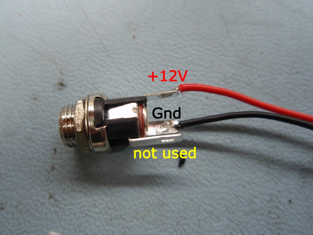
I also have a new battery, so that should help, too. But I have an issue: I'm not sure which wires go where on the power adapter terminals, and on the motherboard itself. One is for GND, and two are for power, correct? Looking for some sort of manual was fruitless. Maybe it's common knowledge, or I'm just missing something... Any help would be appreciated.

Breaking everything, one screw at a time.

24 (edited by kittensauce 2017-01-09 16:17:57)

Re: Replacing the Chumby One screen?

I was browsing Google to see if I could find an answer, and I think I found one (sorry for it being so big, I can't get down this darn BBCode):
http://picprojects.org.uk/projects/rgb/images/dcwired.jpg
That power jack looks pretty similar to the ones I have, so I presume the wiring would be the same. Though, I'm a bit confused by the "not used" terminal - surely, every terminal has a purpose? The Chumby One jack has four solder points, so it must be used. However, my jacks only have three terminals, not four, which only confuses me further. Could someone with more knowledge of this type of thing please help me out here? smile

Breaking everything, one screw at a time.

Re: Replacing the Chumby One screen?

Some sockets may have a switch built into them, so circuitry can be designed to behave differently when there is something plugged into them (e.g. mute/disconnect the loudspeaker when the user plugs in a set of headphones). I don't know whether that's the case with the Chumby socket which uses a different kind of plug than a headphone jack, but it's a fairly likely explanation for the extra terminals on the socket.