Sorry for not replying sooner; I've been busy being lazy. 
Also, I was away from my Chumby for a while. Probably doesn't have anything to do with my laziness, though.
Thank you for all the replies, though! It's good to see that this old alarm clock isn't quite dead yet (and hopefully never will be)!
Materdaddy wrote:As for the NTSC/PAL, I believe the same pads are used, but there are code changes to differentiate. Unfortunately the picture itself is gone, but maybe one of the admins has a copy. I looked in my mirrors and old files and didn't find it but you can read what is available here:
-snip-
I've actually seen that page before, that's where I got the idea to attempt such a feat in the first place 
I've also managed to find the image (it's on bunnie's blog), but it seems that the image was of the older motherboard (see below), and I apprently have the newer 10.8 motherboard.
Duane wrote:There were two C1 devices, the difference being a different factory that was manufacturing them - actually there was a third one, a prototype, but I don't think there are any in the wild.
I believe the first will show as HW 10.6, and the other as HW 10.8, and there are close to the same number of each in the field. One way to tell the difference is the the blue band on the front is a little wider in the 10.8 version. The same factory that built the 10.8 version also built the C8. The 10.6 version was built by the factory that built the I3.5 and I8. I think the 10.8 version also came with a better power supply.
I suppose I have the 10.8 version... because I don't have the 10.6 version? At least, from what I've seen, 10.6 boards say "HW Code 10.6", and since mine doesn't say that... well, I think you get the idea.
Although, it doesn't say "HW Code 10.8" either, which is a little strange.
Duane wrote:The internal electronics are more or less the same.
Except for the location of the video out pins, apparently - unless I'm just missing them?
Duane wrote:The device will work just fine without the microphone attached.
That's a relief, I thought I had bricked my Chumby! (Because the 3DS doesn't turn on with the microphone, and I've only ever had a look at a 3DS motherboard - I just thought they were a little similar. Fortunately not!)
Doktor Jones wrote:For the short distance you're running it, 30AWG will probably make do (I calculated the voltage drop to be <0.1V for about 3 inches), but if you have anything larger (I'd suggest at least 24AWG, such as one of the conductors from CAT5 cable) that would be better. Doesn't matter much if it's stranded or solid, and yes rosin core solder is fine, that's what's used in all electronics -- acid core, on the other hand, should only be used for plumbing!
Alright, thank you - it's a good thing those are the only soldering materials I have! (Rosin core and 30AWG/24AWG wires)
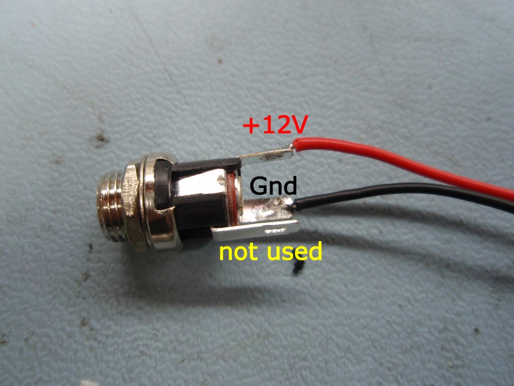
Doktor Jones wrote:If you're comfortable doing so, you may look into removing the jack from the board entirely; I had a laptop whose jack suffered the same fate, and I removed it and put a panel-mount jack in the laptop's case with a pigtail running directly to some nice large power contacts on the board. Of course this tethers the board to the case, but it's a more mechanically sound solution, as the connect/disconnect force is borne by the case instead of a couple of soft bits of metal 
Should you do the above, try to use at least 20-22AWG, and keep the pigtail long-ish (maybe a foot or so) so if you need to crack it open again you have some room.
I'm sorry, I'm not quite sure what you mean. Should I remove the jack and then somehow put a new jack on the case itself instead of the motherboard? And if I go through with this procedure, would the battery still function?
Breaking everything, one screw at a time.


 Blue Buddy